| |
The main parameters of this design were:
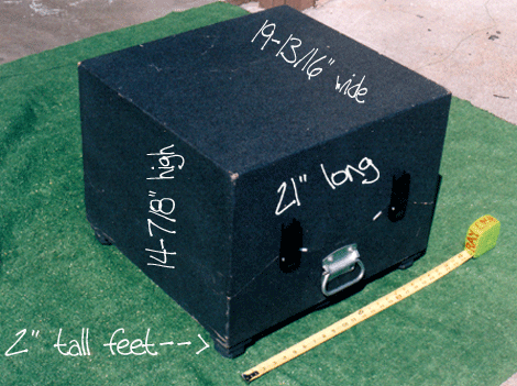
Compactness when packed. I had to keep the width, height, and
length to total no more than 62" (the limitations on most commercial
airlines). I ended up totaling out at 57-13/16". I do have to remove my focuser
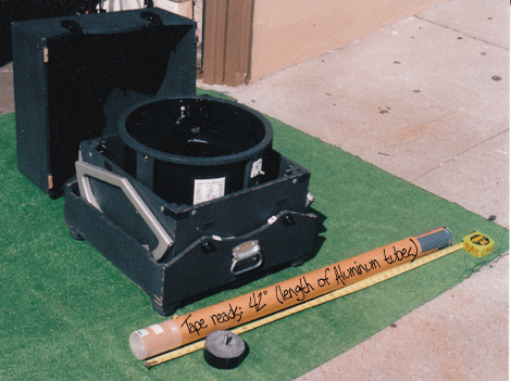
(attached with tiny butterfly nuts), a lead weight (pictured) and my QuikFinder (one-power
reflex finder) when completely packed. These items can be packed (with shroud as packing
material) in the empty spaces of the nested boxes.
The weight, too, had to be limited to 70 lbs., for the same sort of
airline restrictions. It turns out that with the Primary left in the Mirror Box, I total
out at a little over 70 lbs. However, when flying, I take out the Primary and carry it on
board (even with the protective box I made for it, it still fits within my
"messenger-style" bag). The aluminum tubes can be carried on too, or checked in.
I wanted the scope to be sturdy; to survive many hostile encounters with
airline baggage personnel and machinery.
I wanted the scope to look good; to exhibit my craftsmanship.
Ease of assembly was important: "No tools" setup preferable.
Ease of key replacement parts was also in the equation...
What if the truss tubes were lost in transit, or damaged? Could I easily
replace them at the other end?
General Construction Notes and Tips:
These "plans" are not for the novice woodworker. No way can I
"hold your hand" through every process of making this scope--or one similar to
it--via email. You must be willing to solve problems for yourself! And--to repeat--I
expect you to already have some woodworking skills, tools, and "dead tree"
resources.
Lastly; these notes are not complete; I am outlining the parameters of
this design; I am providing you with photos and dimensions; I am telling you what I would
have done differently... I am not providing you detailed CAD drawings, a cut
list, a plywood cut pattern, or extensive links to sources. All of these things I
plan to do in the future: This site is still very much "under construction."
...So please be patient, and do some of the footwork yourself; at least for now.
If you want to use these plans around a 12.5" mirror, I am sure they
would work.
Construction material used throughout is: 1/2" Baltic Birch
Plywood. This plywood is the finest in the world; the plies are even thickness throughout,
and are glued up with marine-grade glue (waterproof). This plywood is, however,
expensive and heavy. Domestic "Apple Ply" would be an excellent choice, too.
The Altitude Bearings are made of 3/4" MDF (Medium Density
Fiberboard), faux finished to look like aluminum and the bearing surface laminated with
Wilsonart's Ebony Star plastic laminate.
The finish is Zolatone: "charcoal
matrix."
I worked from the top down, making the UTA (upper tube assembly) first;
so that it would nestle into the Mirror Box, then the Mirror Box would nestle into the
Rocker Box...
Whenever I needed to, I drew a full-scale drawing on a piece of
cardboard. Especially helpful when determining the angle and length of your truss
tubes, as well as determining "swing through" clearance for the Mirror Box and
the Rocker Box. Also helpful for the mirror cell, both plan (top view) and side section.
I did not worry about the balance point, or where the center of gravity
would lie (ideally this would coincide with the center of the Altitude Bearings), for
altitude movement since compactness had to be foremost in this design. As it turns out, I
had to add a lead weight (removable, as seen in some of the photos)... I melted down about
five pounds of lead in a coffee can and stuck a 5/16" bolt in it while it was still
molten. A mating 5/16" T-nut was placed in the bottom of the Mirror Box. (See my
sub-page "Things I Would Have Done Differently" for a better approach).
I used 3/4" outside diameter seamless aluminum tubing. The
tubes are interchangeable, but there is a top and bottom to them. I taped black
electrician's tape to the inside surface to help eliminate any stray light. My tubes
worked out to be 42" long--but always cut them long first, you can always make longer
ones shorter; not vice versa!
Miscellaneous fasteners: 1/4 X 20 T-nuts; 1/4 X 20
Threaded Inserts; Hand Knobs (ordered from Reid Tool
Supply Company); 1/4 X 20 Threaded Rod (to mate with Hand Knobs using Loctite);
1/4 X 20 Floor Levelers.
|
|

