The Mirror Box             


The Mirror Box, as Tom Clark says, is the unsung hero of truss-Dobs. TMB has many functions: to house, support, and enable access (and collimation) to the primary, provide secure attachments for the trusses and altitude bearings; to be strong, light, and compact.

A view of my Mirror Box in the semi-packed position. The Altitude Bearings are removed and tucked into the front and back of the Rocker Box, which is made wider to accommodate them (the sides of the Rocker Box are narrower so the Altitude Bearings will work!)

I made an elevated light baffle which the mirror cover "Velcro's" on to. The cover is recessed in the middle to accommodate the diagonal when the UTA is nestled on top... not something I planned on; a little "surprise" I had to design around!


mbox1g.gif (76058 bytes)


            altg.gif (62627 bytes)


The removable Altitude Bearings.

This "less-than-half-a-circle" approach seems to be my trademark.  You are free to copy--but figure it out for yourself!  These are attached with two 1/4 X 20 "floor levelers" (shown) and two "threaded inserts." The bearing surface is lined with Wilsonart's Ebony Star (brand, and kind) plastic laminate. Screws with finish washers at both ends insure the plastic laminate (with contact cement) will stay there, as well as provide positive stops so the scope won't simply "roll past" the bearing surface.

Note that the radius does not extend past the Mirror Box, and the center is in the middle of the "spokes," not the edge--this is especially important if you decide to add Digital Setting Circles.


My lower truss clamping system.

When designing a nesting truss-Dob, it is best to have the trusses attach on the inside of the Mirror Box, this way the four planes that the eight trusses form will all be vertical and perpendicular to each other; not splayed outward--or inward--in other words (not that this can't be done). Furthermore, with this design approach, you will have room to nest the UTA inside the Mirror Box.

However, you do not have much room in those corners to accommodate clamp blocks... The method I finally adopted was a simple one: 1/4 X 20 through bolts into the (unflattened) aluminum trusses. I drilled an oversize hole in the aluminum (very hard to drill accurately in round, hollow aluminum), then I stuck a square  piece of maple (hard wood) (which I had previously drilled accurately) in the hollow aluminum tubes. I secured the square wooden blocks with small screws.

mbox3g.gif (73385 bytes)

The rectangular blocks you see in the corner help maintain the
angle of the trusses until I get the UTA attached (otherwise, it is pretty floppy).

You can also see in this photo one of the two floor levelers holding the Altitude Bearing in.


          mbox2g.gif (66696 bytes)


More dimensions of the Mirror Box (and Rocker Box). [Correction: that 19-7/8" dimension should read: 19-13/16"]

The 45-degree angle on the one corner of the Mirror Box was necessary for such a low profile Mirror Box to clear an equally low profile Rocker Box--these dimensions were determined with a full-scale layout.

Note: A "piano hinge" is attached at the lower part of the "3-9/16" dimension (it does not show up on the photo well)... This enables the "tailgate" to open up (see following).

Note that I have also lined with Ebony Star a small curved portion of the Mirror Box just beneath the Altitude Bearing--this allows Teflon to rub against this surface, instead of paint.


mbox4g.gif (62359 bytes)

tailgateg.gif (60612 bytes)


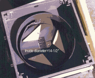
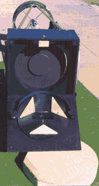
A couple more views of the Mirror Box. At left, with mirror cover removed, you can see the nine-point mirror supports and sling. For the correct placement of these points, I used David Chandler's freeware program "Cell."  For details on how to make a simple sling, mirror clips, and cell, I recommend The Dobsonian Telescope by David Kriege and Richard Berry; this book will answer any questions you have about making a truss-Dob, and much more.

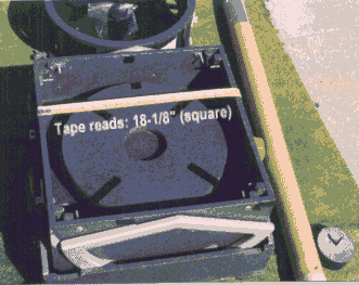
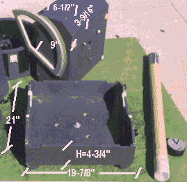
Note that I have a light baffle (made of 1/8" Italian Poplar plywood) elevated 2-1/2" off an "intermediate deck" which is 5-1/4" below the top edge of the Mirror Box.

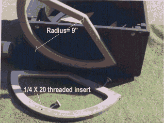
At right you see the "tailgate" open. When closed two "floor levelers" keep it shut (the floor levelers screw into 1/4 X 20 threaded inserts). 
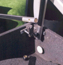
That unpainted block at the top inside of the Mirror Box is a captured spring-loaded block, faced on one edge with cork: When traveling short distances (not flying, in other words) I leave the mirror inside the Mirror Box and unscrew this block from the outside; this allows the block to put a little pressure on the mirror and helps prevent it from flopping around. At the observing site, I screw this spring-loaded block in so the mirror is free to move.


NEXT Page (The Rocker Box)         
TABLE OF CONTENTS        
HOME