My 13, 17.5, and equatorial platform
Things I Would Have Done Differently
My 13, 17.5, and equatorial platform
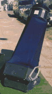
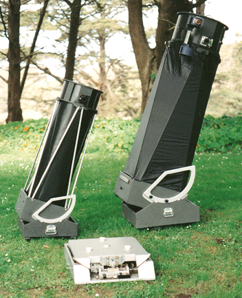
| I was so pleased with the looks and functionality of my travelscope, I decided to rebuild my 17.5 along similar lines; to create a 'big brother,' so to speak. Of course, one never quite travels the same path twice, and I found myself adding improvements to the design I was already pleased with. |
|
You will immediately notice I used an external shroud rather than the internal one (that was made of Kydex, by the way) on the 13... I have since changed the 13 over to an external one, too. The material I like to use (after several experiments) is called Neoprene. This material is a little heavy, but it is very black on the inside, attaches easily with Velcro (the 'hooks' on Velcro sticks to the fuzzy black inside of Neoprene), stretches in one direction, and provides excellent packing material when the scope is disassembled (there is plenty of empty space in which to pack eyepieces and such, within the scope). I also added a light baffle (in front) made of Kydex that simply "Velcro's on." |
| The major annoyance with this scope is its eyepiece/focuser position. Because of its relative low height, this six-foot tall person finds himself bent over uncomfortably when looking at things (like the planets) below 45-degrees in azimuth. I should have located the focuser in a canted position, say 20-30 degrees, instead of being parallel with the ground. As it is, I often simply place the whole scope on its Lid to save my lower back the pain accompanying that awkward position! (My 17.5, being taller already, does not present this problem).
|
|
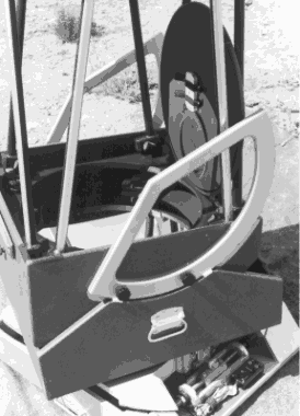
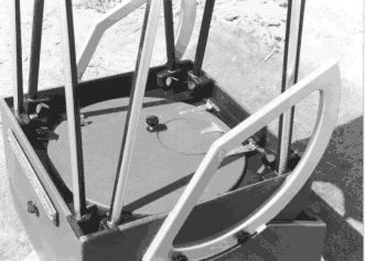
| At right are a couple of black and white photos of my 17.5's Mirror Box. Note the hand Knobs on the outside of the Altitude Bearings: I used T-nuts to attach them--a more secure attachment--rather than the Threaded Inserts I used extensively on the 13. There are also stubby dowels in the Altitude Bearings which help locate, and give more support to, these structural pieces.
|
|
| Also, on the 17.5, I am very happy with my mirror cover/stop-down mask,
and wish I would have incorporated something similar on my 13. The entire cover is hinged:
when opened, it latches onto one of the truss tubes using one of those snap-in broomstick
holders found in every hardware store (just peeking out from behind the third truss tube
from the left in the above photo). If I want to "stop-down" my 17.5 to
6" (for planetary observation, let's say), I close the cover and open up the six-inch
hinged cover which is integral to the larger cover: This works very well--and very
quickly! That thing you see strapped to the inside of my cover, by the way, is a reusable dessicant purchased at my local photo store. This helps ensure no harmful moisture resides in my Mirror Box.
|
|
|
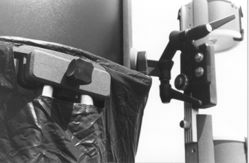
I can't say I am completely happy about the truss clamping system I used
on the 13. On the 17.5 (where limited space really was not a concern), I used a
more trouble-free and secure "split-block" method both at top and below. At left
you see two lower clamps: one in "operation," and one taken apart to show you
its construction. Going from left to right with the "taken apart" one: a
"slot" to accept a dowel (which is glued in the other half)--this acts as a
hinge and locator for the loose half of the clamp block; a conical, collapsable spring
(with hand knob bolt poking through--T-nut in fixed half). On the right of the truss,
there is a dab of silcone to aid springing the block apart to remove or insert truss. The
block does not need to come apart completely to insert the truss. Blocks must be made for
left and right, and should be carefully laid-out, holes drilled, etc.on one stick:
The last thing you do is slice the stick in half, then chop into individual blocks. Be
sure to label the pairs, lest you mix up the pieces!
|
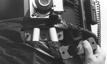
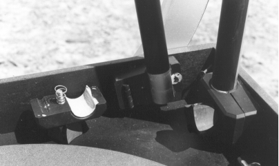
| A couple views of the upper clamp block set-up. These, too, remain
one long "stick" until they are finally sliced in half and cut into individual
pairs. Please ignore my early, wrinkled shroud! Dowels are for locating the loose half, and prevent turning of that half. Again, no need to take apart like this for insertion or removal of trusses. Note also the chamfer in the holes (just above my thumb, for example): these help in inserting the trusses (the lower blocks are similarly machined, by the way). The angle of the drilled holes can be determined by a full scale layout of your telescope. Even if you are a degree or so off, the clamps will still work beautifully. Use a tilting Drill Press, or make an angled jig for drilling the holes if your Drill Press does not tilt. That's a little block of rubber, above and to the left of my thumb. You gotta set the UTA down on the ground sometimes! The rubber block helps keep the truss blocks clean and free of gravel, is all.
|
|
| Adding a weight at the back end of the Mirror Box of the 13 was an inelegant solution. Perhaps a spring-loaded "virtual weight" as K. Barry Peckham uses with his Litebox designs, is a better solution. (However, with my low profile Mirror Box, this may not work, either). When "scaling up" this design to my 17.5, by the way, I did not worry about balance problems, either: It turned out (because of the much more massive 17.5) that I was actually bottom heavy; which just meant I could hang more "accessories" off the UTA. |